 How Disk Brakes & Drum Brakes Work
Brakes
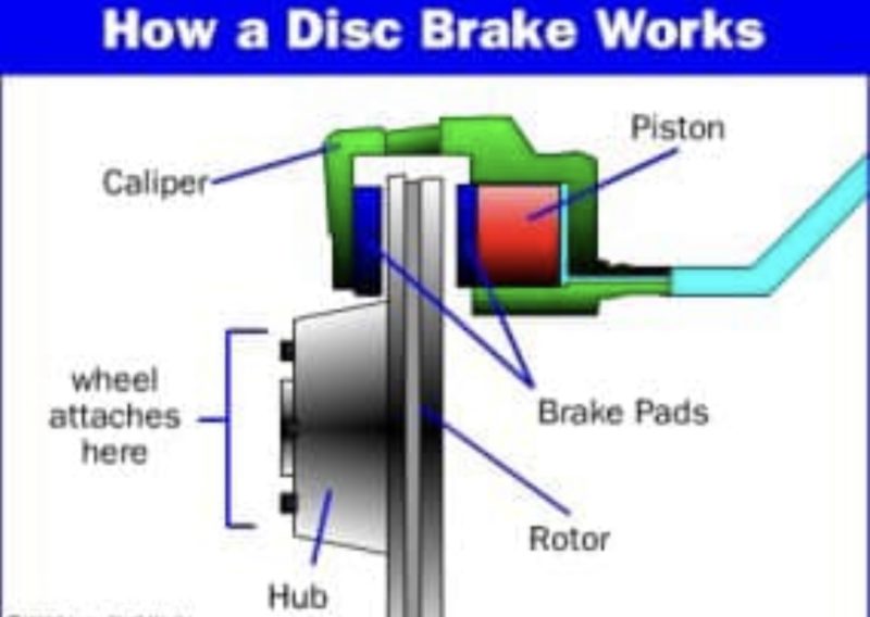
Most automotive brakes have a caliper, which squeezes the brake pads against the wheel. In a disc brake, the brake pads squeeze the rotor instead of the wheel, and the force is transmitted hydraulically instead of through a cable. Friction between the pads and the disc slows the disc down.
Drum Brakes
A drum brake system consists of hydraulic wheel cylinders, brake shoes and a brake drum. When the brake pedal is applied the two curved brake shoes, which have a friction material lining, are forced by hydraulic wheel cylinders against the inner surface of a rotating brake drum.
HOW DOES A BREAK BOOSTER WORK
 The booster works by pulling the air out of the booster chamber with a pump creating a low pressure system inside. When the driver steps on the brake pedal, the input rod on the booster is pushed in which lets atmospheric pressure into the booster. This, in turn, pushes the diaphragm toward the master cylinder.
In terms of functionality, a brake booster does the same for a braking mechanism what power steering does for steering. The recent addition to the automobile brake systems is designed to improve braking performance and safety. With a brake booster, the driver does not need to exercise excessive force on the brake pedal when stopping the car.
Brake Booster Definition
Crucial to the functionality of the vehicle and safety of passengers, a brake booster looks like a black circular-shaped canister. It works with the master cylinder to give higher pressure to the brakes, thereby reducing the amount of pedal pressure required for braking.
The device sits on the back area of the engine case, specifically between the pedal and the master cylinder. It uses a vacuum to balance the high fluid pressure in the braking system of a vehicle, facilitating effective braking.
When the brake pedal receives pressure from the driver, a shaft attached to the power brake booster moves forward, thrusting a piston to the main brake cylinder. As a result, brake liquid passes through the braking system. The brake booster, on the contrary, gives the pedal enhanced strength by using the engine vacuum, counterbalancing the braking system’s high pressure.
When the liquid reaches the wheels after passing through the brake cylinder, it clasps the brake rotors’ pads, slowing down the vehicle. The frictional force works in transmitting the energy from the brakes to the tires, and then to the road.
The Advantages of Using Brake Boosters
The major function of brake boosters is to increase the power applied to on the pedal. You will need to exercise a tremendous amount of pressure to slow down and stop your car if there is no brake booster. So, it is a blessing for those people who does not have a healthy physique or who have to drive a lot as they no longer need to wrestle down with the brake pedal. Besides, easy braking with just a little amount of pressure on the pedal reduces the risk of accidents.
Photo Credit: Brake Booster
Brake Booster: How It Works
Brake boosters are available with two different diaphragms – single (for smaller vehicles) and tandem (for bigger cars and trucks). They work by multiplying the force exerted on the brake pedal. When the driver presses the brake pedal, a liquid transmits that pressure to the brakes. However, even that amount of force is not enough to stop the car. So, the brake booster multiplies that force to 2-4 times the size of the diaphragm.
Link/Credit: https://www.google.com/amp/s/carfromjapan.com/article/car-maintenance/brake-booster-works-braking-system/amp/
HOW DOES A MASTER CYLINDER WORK
When you press the brake pedal, it pushes on the primary piston through a linkage. Pressure builds in the cylinder and lines as the brake pedal is depressed further. The pressure between the primary and secondary piston forces the secondary piston to compress the fluid in its circuit.
INTRODUCTION:
“Great things are done by a series of small things brought together” very rightly said as when it comes to automobiles even a small components like sprockets, valves, piston rings etc. Have great impact on overall working of an automobile vehicle. We often talk about the components and forces that help the vehicle to speed up or to perform. But have you ever think about the amount of force required to stop the vehicle at such a high speed?.Now this question gives rise to many other questions like from where does this high force generated? , which component is responsible for this high stopping force? So let’s just discuss about the component responsible for generating this high brake force i.e. Master cylinder.
Master cylinder in an automobile braking system is a hydraulic device in which cylinder and one or two pistons are arranged in such a manner that the mechanical force applied by the driver of a vehicle either by brake pedal (in cars) or by brake lever (in bikes) is converted into hydraulic pressure which in turn transferred to the brake caliper for braking.
In hydraulic braking system, master cylinder is a device that provides required amount of pressure or braking force to the final braking components after multiplication of the mechanical force applied by the driver through brake pedal or brake lever.
Why We Need a Master Cylinder
As we all know now that a master cylinder in hydraulic braking system is an intermediate component that worked as an energy converter as well as force multiplier i.e. mechanical energy into hydraulic pressure so we need master cylinder in hydraulic braking system because-
- When we talk about today’s automobile vehicles due to their high speed, the brake force required (to stop or de-accelerate vehicle efficiently) is also high, which cannot be efficiently fulfilled by mechanical braking, so hydraulic braking with master cylinder is the new need of today’s vehicle as it generates higher brake force.
- As we all know that the brake force required in front wheels is higher than that of real wheels due to the shifting of mass from rear to front during braking, this distribution of brake force between rear and front wheels is a function of master cylinder.
- In hydraulic braking, the force applied by driver on brake pedal (in car) or brake lever (in bikes) during braking (50N-70N) is not enough to cause actual braking, so an intermediate component i.e. master cylinder is required that can multiply this force and further transfer this high force to the brake caliper which in turn generates high brake force and finally actual braking happens.
- In hydraulic braking the brake pedal or lever effort required for braking is drastically decreased due to the use of master cylinder as it acts as a converter that can convert the mechanical force applied by driver on brake pedal or lever into the high hydraulic pressure.
- The use of master cylinder decreases the chances of brake failure as it provides the constructional flexibility in which the braking in front and rear tire can be made independent of each other.
Types of Master Cylinder
On the basis of its construction and application brake master cylinders are of 2 types that are-
1. Single Circuit Master Cylinder
- It is the simple type of master cylinder just like a medical syringe, in this type of master cylinder single piston inside a cylinder is used to cause braking.
- Single circuit m c (master cylinder) distributes equal force in all the wheels due to the use of single cylinder single piston or circuit.
- This type of master cylinder is commonly used in many 2 wheelers and some light weight 4 wheelers
2. Tandem Master Cylinder or Dual Circuit Master Cylinder
- It is the modified type of m c in which dual cylinder-dual piston or single cylinder dual piston along with dual circuit is used for independent braking between front and rear wheels.
- This type of master cylinder is used in almost all cars as it is more efficient than single circuit m c.
- It provides the independency between front and rear wheels braking or diagonal type of braking which is the important safety feature for a vehicle.
Construction
Single Circuit Master Cylinder
It consist of 5 parts :
1. Reservoir
It is the storage tank used for storing the brake fluid in hydraulic type of braking system, usually it is made up of plastic.
2. Cylinder
It is the air tight housing inside which the piston moves with the moment of brake pedal which in turn causes conversion and multiplication of force. Cylinder is usually made up of cast iron or aluminium.
- It is connected with the reservoir through inlet valve and also with brake lines through outlet valve.
- In single circuit m c there is only 1 compression chamber.
3. Piston
It is the reciprocating part of the master cylinder that reciprocates inside the cylinder due to the movement of brake pedal, the piston causes compression of brake fluid inside the cylinder which in turn generates high hydraulic pressure.
- In single circuit only 1 piston is used.
4. Returning Spring
It is the simple coil type of spring used inside the cylinder which helps the piston and brake pedal to retain its original position after brake pedal is released.
5. Valve
In single circuit m c it is the outlet valve through which the brake line is attached, The compressed brake fluid is further transferred to the caliper through this valve.
Tandem Master Cylinder
1. Reservoir
In tandem master cylinder instead of single reservoir 2 or dual chamber reservoir is used as a storage tank for brake fluid.
2. Cylinder
Same cylinder as in single circuit type is used with the little modification i.e. it is the housing of 2 pistons and also there are 2 outlet and 2 inlet valves.
- In tandem m c there are 2 compression chamber inside the cylinder.
3. Piston
Instead of one piston, 2 pistons that are primary piston and secondary piston are used in tandem m c, the actuation of secondary piston occurs after completion of the primary piston movement.
- primary piston is connected to the brake pedal and secondary piston is placed just behind the returning spring of primary piston.
4. Returning Spring
In tandem m c 2 returning springs are used one with the primary piston and second with the secondary piston.
5. Valves
In tandem master cylinder as it is the dual circuit m c , 2 inlet and 2 outlet valves are used .
Working
Single Circuit Master Cylinder
- In single circuit master cylinder when brake pedal is not pressed i.e. non actuation position the piston remains at its original position which in turn closes the inlet valve of the reservoir due to which there is no incoming of brake fluid takes place between reservoir to compression chamber.
- When brake pedal is pressed i.e. actuated position, the piston which is connected to the brake pedal through connecting rod moves which in turn opens the inlet valve due to which incoming of brake fluid from reservoir to compression chamber takes place.
- This brake fluid inside the compression chamber is compressed due to the movement of piston inside the cylinder just like the medical syringe.
- After compression up to a certain pressure the outlet valve opens and this highly compressed brake fluid is further transferred to the brake lines for further brake actuation.
Tandem Master Cylinder
The working of tandem master cylinder is 70% same as the single circuit m c but in this type 2 independent circuits of braking is used let see how its work-
- When brake pedal is not actuated, the piston remains at their original place, closing the inlet valve of both the compression chambers, which in turn cuts the incoming of brake fluid between both the reservoir or both the reservoir chambers.
- When the brake pedal is actuated, at first the primary piston moves due to which opening of primary inlet valve takes place.
- Initially due to the movement of primary piston compression of the brake fluid inside primary chamber takes place.
- After completion of the compression in primary chamber primary outlet valve opens up and this compressed brake fluid is further sent to brake callipers through brake lines and actuation of the primary circuit brakes take place.
- After the completion of the primary piston movement i.e. at its extreme end, the secondary piston starts moving because of the force applied by the primary piston’s spring which in turn opens the secondary valve and incoming of brake fluid from secondary reservoir to secondary compression chamber takes place.
- This brake fluid is then compressed and after complete compression secondary outlet opens up and this highly compressed fluid is sent to the brake callipers through brake lines and actuation of the secondary circuit brakes take place.
Application
Single Circuit Master Cylinder
- It is mainly used in 2 wheelers like Bajaj pulsar, TVS apache etc.
- Many light weight vehicles like e-rikshaws are also using this type of master cylinder.
Tandem Master Cylinder
- It is widely used in almost all the cars equipped with hydraulic braking system.
- Using tandem master c in vehicle equipped with hydraulic braking system is made compulsory by governments of many countries because of its safety to brake failure.
Credit/Link:https://www.mechanicalbooster.com/2018/05/what-is-master-cylinder.html
How Does Anti-lock Braking System (ABS) Work?
How Does Anti-lock Braking System (ABS) Technology In Cars Work? ABS prevents the wheels from locking up, thus avoiding uncontrolled skidding of the vehicle and decreases the distance traveled without slipping. Without an anti-lock brake system, the wheels of your car stop spinning and the car will begin to skid.
Breaking Down Anti-Lock Brakes
- A) Pump the brake, or B) hold the brake down firmly.
The correct answer depends on whether the car you’re driving has an anti-lock braking system, or ABS. It’s a safety system that pulses the brakes many times per second so that they don’t lock up. When the brakes don’t’ lock up, you are able to control the steering better.
Drivers who learned to drive before ABS became standard likely learned to pump the brake pedal during emergencies and slippery conditions. ABS takes away this requirement; but some who learned the pump method may question the need for ABS.
The National Highway Traffic Safety Administration (NHTSA) made ABS a mandatory feature for new cars starting September 2011. ABS provides driver more control through steering during braking by not locking the brakes.
Unless you live in a snowy and icy state, you seldom will get to feel ABS activate. When it does, it vibrates and groans. Drivers report that they feel like their brakes have failed. The vibration you feel is just the brakes pulsing the brakes many times a second.
How does ABS make you safer than just pumping the brakes on your own? What’s going on when your car’s ABS activates? Read further for answers to these questions and more.
What’s the secret behind anti-lock brakes?
When it comes to explaining the power of ABS, NHTSA says it best in a 2013 “Question and Answer” document:
“When faced with a panic braking situation, ABS allows a driver to rapidly apply the brakes without worrying about wheel lockup, and the vehicle begins to stop immediately. Without ABS, a rapid, hard brake application could cause wheel lockup and loss of vehicle steering control, if the driver does not pump the brakes correctly or limit the brake pedal force to prevent wheel lockup. Therefore, more driver skill is needed to obtain short stops without ABS.”
So, ABS can pump faster than a driver can, but how?
Simply put: Physics, modern computing and a whole lot of “oomph.”
When ABS is working properly, the driver may feel the brake pedal suddenly drop, followed by a rapid pulsing sensation. There may be a grinding or buzzing noise coming from the vehicle during the period ABS is activated. It may also feel like the brake pedal is pushing back when ABS activates.
ABS: The brakes that help you steer
You read that right – ABS is not just about braking, it’s also about steering.
In fact, steering is the primary safety function of ABS during emergencies, according to NHTSA:
“[Question:] Do cars with ABS stop more quickly than cars without? [Answer:] Perhaps, but that’s not the main purpose of ABS. It is a system designed to help you maintain control of the vehicle during emergency braking situations, not necessarily make the car stop more quickly.”
According to the Insurance Institute for Highway Safety (IIHS), on very slippery surfaces ABS can actually increase a driver’s stopping distance. These include surfaces with loose gravel or lightly packed snow. These materials can create a “dam effect” in front of the wheels that are locked up, preventing the vehicle from stopping as quickly as a vehicle without ABS would.
A literal lifesaver in a pinch
According to Liberty Mutual, by 2004 ABS was considered the second most important car safety feature after the safety belt. Other modern safety features – such as electronic stability control and automatic emergency braking – may eventually also rise to near the top of the list; but the lengthy history of ABS makes it a legend in the realm of car safety technology.
One of the most extensive studies of the life-saving benefits of ABS was a NHTSA study published in 2009. NHTSA analyzed crash data from 1995 to 2007, a 12-year period after which NHTSA conducted a large public information campaign on using ABS properly. ABS also came to be available as a standard or optional feature most new vehicles sold in the United States during this time.
According to the study, between 1995 to 2007:
- Anti-lock braking systems reduced the number of crashes among passenger cars by about 6 percent and by 8 percent for light trucks and vans.
- Anti-lock braking systems were especially beneficial on wet roads, reducing wet-road collisions by 12 percent among passenger vehicles.
- Fatal crashes between passenger vehicles with ABS and pedestrians, bicyclists and animals decreased 13 to 14 percent.
Getting to know your ABS
In 2017, most cars on the road have ABS. To check, turn your car to the accessory mode and see if the there is an ABS icon. If it’s there, your car has ABS.
All drivers should really get to know their ABS and understand how it works and what’s happening when it’s activated.
Credit/Link:https://mycardoeswhat.org/breaking-anti-lock-brakes/
—Air Brake Systems – How They Work
AIR BRAKES:
Air brakes are used in trucks, buses, trailers and semi-trailers. This is the preferred type of braking system for these vehicles for several reasons. First, the use of air allows multiple vehicle units to be coupled so that all units have braking capability and so that all of those units’ brakes may be controlled from the cab. Coupling would be infeasible if a liquid were used as the mode of transmission of force, as it is in hydraulic brakes. In addition, the use of an air brake system allows for the incorporation of an emergency braking system that utilizes parts of the service brake and parking brake systems. Emergency braking systems are required on all semi-trailers by CFR 49 393.43, as it states “Every motor vehicle, if used to tow a trailer equipped with brakes, shall be equipped with a means for providing that in the case of a breakaway of the trailer, the service brakes on the towing vehicle will be capable of stopping the towing vehicle.”
Air brake systems are three braking systems combined:
- The service brake system applies and releases the brakes when one uses the brake pedal during normal driving.
- The parking brake system applies and releases the parking brakes when one uses the parking brake control.
- The emergency brake system uses parts of the service and parking brake systems to stop the vehicle in the event of a brake system failure.
The air brake system:
An air brake system uses air as a way to transmit pressure from the driver’s control to the service brake. It also includes an air-over-hydraulic brake system.
Air compressor and governor:
The air compressor pumps air into the air storage tanks (reservoirs). The air compressor is connected to the engine through gears or a V-belt. The compressor may be air cooled or may be cooled by the engine cooling system. It may have its own oil supply, or be lubricated by engine oil. If the compressor has its own oil supply it has to be checked regularly. The governor controls when the air compressor will pump air into the air storage tanks. When air tank pressure rises to the “cut-out” level (no higher than 135 pounds per square inch, or psi or 900 kPa), the governor stops the compressor from pumping air. When the tank pressure falls to the “cut-in” pressure (no lower than 85 psi or 590 kPa), the governor allows the compressor to start pumping again.
Air Dryer:
Today, most vehicles that use air brakes are equipped with an air dryer. An air dryer is used to take the moisture out of the air, so that water condensation will not build up in the air storage tanks and cause the brakes to fail, such as when the water freezes in the winter.
Air Storage and Drain Tanks:
Air storage tanks are used to hold compressed air. The number and size of nair tanks varies among vehicles. The tanks will hold enough air to allow the brakes to be used several times even if the compressor stops working. Compressed air usually has some water and some compressor oil in it. This is bad for the air brake system. For example, the water can freeze in cold weather and cause brake failure. The water and oil tend to collect in the bottom of the air tank. Each air tank is equipped with a drain valve in the bottom. There are two types:
- Manually operated by turning a quarter turn, or by pulling a cable. One must drain the tanks his or herself at the end of each day of driving. Automatic. The water and oil are automatically expelled from the valve (these valves are equipped for manual draining as well).
- Spit valve. The water and oil are automatically expelled from a spit valve. The type of valve “spits” out water and air each time the governor cycles. The automatic types are available with electric heating devices. These help prevent freeze up of the automatic drain in cold weather.
Alcohol evaporator:
- Some air brake systems have an alcohol evaporator to put alcohol into the air system. This helps to reduce the risk of ice in air brake storage tanks, valves, and other parts during cold weather. Ice inside the system can cause brake failure.
Safety valve:
- A safety relief valve is installed in the first tank the air compressor pumps air into. The safety valve protects the tank and the rest of the system from too much air pressure. The valve is usually set to open at 150 p.s.i. (1030 kPa)
Brake pedal:
The brakes are applied by pushing down the brake pedal (also called the foot valve or treadle valve). The harder you push down on the pedal, the more air pressure is applied from the storage tanks into the brake chambers. Letting up on the brake pedal exhausts the air pressure from the brake chambers and releases the brakes. The air pressure used to apply the brakes must be built up in the reservoirs by the compressor. Pressing and releasing the pedal (fanning) can unnecessarily let air out faster than the compressor can replace it. If the pressure gets too low, the brakes will not work. When the brake pedal is pushed down, two forces push back against the driver’s foot. One force comes from a spring in the valve. The second force comes from the air pressure going to the brake chambers. This lets the driver feel how much air pressure is being applied to the brake chambers. However, this “feel” does not tell the driver how much force is being applied to the brakes because that depends on brake adjustment.
Drum brakes:
Drum brakes (foundation brakes) may be used at each wheel. The most common type is the S-cam drum brake (so called because of the mechanism that applies force to the brake shoes). Brake drums are located on each end of the vehicle’s axles. The wheels are bolted to the drums. The braking mechanism is inside the drum. To stop, the brake shoes and linings are pushed against the inside of the drum. This causes friction which slows the vehicle (and creates heat). The heat a drum can take without damage depends on how hard and how long the brakes are used. Too much heat can cause brake failure.
S-cam brakes:
When one pushes the brake pedal, air is let into each brake chamber (Figure 5-2). Air pressure pushes the push rod out, moving the slack adjuster, thus twisting the brake cam shaft. This turns the S-cam. The S-cam forces the brake shoes away from one another and presses them against the inside of the brake drum. When one releases the brake pedal, the S-cam rotates back and a spring pulls the brake shoes away from the drum, letting the wheels roll freely again. It is a common use in heavy trucks over 15 tonnes of GVW. MAN, Mercedes-Benz, Scania and Volvo is using in their construction trucks.
CamLaster:
The CamLaster brake has two key design differences over traditional S-cam brakes. One feature is a completely internal adjustment system which is designed to continually keep the brake in proper adjustment. S-cam brakes, on the other hand, require an external slack adjuster. The second feature is a unique cam design that applies the brake shoe. Unlike a standard drum brake that has either a single or double anchor-pin brake, CamLaster slides the shoes down an inclined ramp on a cam to evenly contact the brake drum.
Wedge brakes:
* The brake chamber push rod pushes a wedge directly between the ends of two brake shoes. This shoves them apart and against the inside of the brake drum. Wedge brakes may have a single brake chamber, or two brake chambers, pushing wedges in at both ends of the brake shoes. Wedge type brakes may be self-adjusting or may require manual adjustment.
 Disc brakes:
In air-operated disc brakes, air pressure acts on a brake chamber and slack adjuster, like S-cam brakes. But instead of the S-cam, a “power screw” is used. The pressure of the brake chamber on the slack adjuster turns the power screw. The power screw clamps the disc or rotor between the brake lining pads of a caliper, similar to a large C-clamp.
One-way check valve:
This device allows air to flow in one direction only. All air tanks on air-braked vehicles must have a check valve located between the air compressor and the first reservoir. The check valve keeps air from going out if the air compressor develops a leak.
Air supply pressure gauge:
All air-braked vehicles have an air supply pressure gauge connected to the air tank. If the vehicle has a dual air brake system, there will be a gauge for each half of the system or, sometimes, a single gauge with two needles. Dual systems will be discussed later. These gauges tell you how much pressure is in the air tanks.
Application pressure gauge:
This gauge shows how much air pressure you are applying to the brakes (some vehicles do not have this gauge). When going down steep grades, increasing brake pressure to hold the same speed means the brakes are fading. The need for increased pressure can also be caused by brakes out of adjustment, air leaks, or mechanical problems.
Low air pressure warning gauge:
A low air pressure warning device is required on vehicles with air brakes. A warning device which you can see must come on when the air supply pressure drops below 60 psi (414 kPa) or one half the compressor governor cut-out pressure on older vehicles. The warning is usually a red light. A buzzer may also come on. Another type of warning is the “wig wag.” This device drops a mechanical arm into your view when the pressure in the system drops below 60 psi. An automatic wig wag will rise out of your view when the pressure in the system goes above 60 psi. The manual reset type must be placed in the “out of view” position manually. It will not stay in place until the pressure in the system is above 60 psi. On large buses, it is common for the low pressure warning devices to signal at 80–85 psi.
Stop light switch:
Drivers behind a vehicle must be warned when that vehicle’s brakes are being applied. The air brake system does this with an electric switch that works by air pressure. The switch turns on the brake lights when pressure is applied to the brake pedal.
Front brake limiting valve:
Some vehicles made before 1975 have a front brake limiting valve and a control in the cab. The control is usually marked “normal” and “slippery.” When you put the control in the slippery position, the limiting valve cuts the normal air pressure to the front brakes by half. Limiting valves are used to reduce the chance of the front wheels skidding on slippery surfaces. However, they also reduce the stopping power of the vehicle. Front wheel braking is good under all conditions. Tests have shown front wheel skids from braking are not likely even on ice. Make sure the control is in the normal position to have normal stopping power. Many vehicles have automatic front wheel limiting valves. They reduce the air to the front brakes except when the brakes are stepped on very hard (60 psi or 410 kPa or more application pressure). These valves cannot be controlled by the driver. (NOTE: Some vehicles are manufactured with no front brakes.)
Spring brakes:
All trucks, truck tractors, and buses using air pressure to apply the service brakes must be equipped with emergency brakes and parking brakes. The parking brake must be held on by mechanical force (because air pressure can eventually leak away). Spring brakes are usually used to meet the emergency and parking brake requirements. When driving, powerful springs are held back by air pressure. If the air pressure is removed, the springs put on the brakes. A parking brake control in the cab allows the driver to let the air out of the spring brakes. This lets the springs put on the brakes. A leak in the air brake system will generally cause the springs to put on the brakes. Tractor and straight truck spring brakes will come fully on when air pressure drops to a range of 20 to 45 psi or 140 to 310 kPa (typically 20 to 30 psi or 140 to 210 kPa ). Do not wait for the brakes to come on automatically. When the low air pressure warning light and buzzer first come on, bring the vehicle to a safe stop right away while you can still control the brakes. The braking power of spring brakes depends on the brakes being in adjustment. If the brakes are not adjusted, neither the regular brakes nor the emergency/parking brakes will work correctly.
Parking brake controls:
In newer vehicles with air brakes, the parking brakes are set using a diamond-shaped, yellow, push-pull control knob. Pulling the knob out sets the parking brakes (spring brakes), and pushing it in releases them. On older vehicles, the parking brakes may be controlled by a lever.
Anti-compound system:
Some vehicles are equipped with an anti-compound system. This keeps the brakes from being damaged by the compounded forces of the spring and the air, if the driver were to push on the brake pedal with the parking brakes applied.
Modulating control valves:
In some vehicles, a control handle on the dash board may be used to apply the spring brakes gradually. This is called a modulating valve. It is spring loaded so you have a feel for the braking action. The more you move the control lever, the harder the spring brakes come on. They work this way so you can control the spring brakes if the service brakes fail. When parking a vehicle with a modulating control valve, move the lever as far as it will go and hold it in place with the locking device.
Dual parking control valve:
When main air pressure is lost, the spring brakes come on. Some vehicles, such as buses, have a separate air tank which can be used to release the spring brakes. This is so you can move the vehicle in an emergency. One of the valves is a push-pull type and is used to put on the spring brakes for parking. The other valve is spring loaded in the “out” position. When you push the control in, air from the separate air tank releases the spring brakes so you can move. When you release the button, the spring brakes come on again. There is only enough air in the separate tank to do this a few times.
Dual air brake systems:
Most newer heavy-duty vehicles use dual air brake systems for safety. A dual air brake system has two separate air brake systems which use a single set of brake controls. Each system has its own air tanks, hoses, lines, etc. One system typically operates the regular brakes on the rear axle or axles. The other system operates the regular brakes on the front axle and possibly one rear axle. Both systems supply air to the trailer, if there is one. The first system is called the primary system and the other is called the secondary system. Before driving a vehicle with a dual air system, allow time for the air compressor to build up a minimum of 100 psi (690 kPa) pressure in both the primary and secondary systems. Watch the primary and secondary air pressure gauges (or needles, if the system has two needles in one gauge). The low air pressure warning light and buzzer should shut off when air pressure in both systems rises to a value set by the manufacturer. This value must be greater than 60 psi or 410 kPa. The warning system devices should come on before the air pressure drops below 60 psi in either system. If one air system is very low on pressure, either the front or the rear brakes will not be operating fully. This means it will take you longer to stop. Bring the vehicle to a safe stop and have the air brake system fixed.
Combination vehicle air brakes:
The trailer hand valve (also called the trolley valve or Johnson bar) works the trailer brakes. The trailer hand valve is used only to test the trailer brakes. It is not used in driving because of the danger of making the trailer skid. The foot brake sends air to all of the brakes on the vehicle including the trailers. There is much less danger of causing a skid or jackknife when using just the foot brake.
Tractor protection valve:
The tractor protection valve keeps air in the tractor or truck if the trailer breaks away or develops a bad leak. The tractor protection valve is controlled by the trailer air supply control valve in the cab. The control valve allows you to open and shut the tractor protection valve. It will close automatically if air pressure is low (in the range of 20 to 45 psi or 140 to 310 kPa). When the valve closes, it stops any air from escaping and lets the air out of the trailer emergency line which causes the trailer emergency brakes to come on. (Emergency brakes are covered later.)
Trailer air supply control:
The trailer air supply control on newer vehicles is a red 8-sided knob which controls the tractor protection valve. Pushing it in supplies the trailer with air, and pulling it out shuts the air off and puts on the trailer emergency brakes. The valve will pop out and close the tractor protection valve when the air pressure drops into the range 20 to 45 psi. Emergency valves on older vehicles may not operate automatically. There may be a lever rather than a knob. The normal position is used for pulling a trailer. The emergency position is used to shut the air off and put on the trailer emergency brakes.
Trailer air lines:
Every combination vehicle has two air lines—the service line and the emergency line. They run between each vehicle (tractor to trailer, trailer to dolly, dolly to second trailer, etc.).
Service air line (normally blue):
The service line (also called the control line or signal line) carries air which is controlled by the foot brake or the trailer hand brake. The pressure in the service line will similarly change depending on how hard you press the foot brake or hand valve. The service line is connected to a relay valve on the trailer to apply more or less pressure to the trailer brakes. The relay valve connects the trailer air tanks to the trailer air brakes. As pressure builds up in the service line, the relay valve opens and sends air pressure from the trailer air tank to the trailer brake chambers, putting on the trailer brakes.
Emergency air line (normally red):
The emergency line has two purposes. First, it supplies air to the trailer air tanks and secondly, the emergency line controls the emergency brakes on combination vehicles. Loss of air pressure in the emergency line causes the trailer emergency brakes to come on. The pressure loss could be caused by a trailer breaking loose, tearing apart the emergency air hose. It could also be caused by a hose, metal tubing, or other part which breaks, letting the air out. When the emergency line loses pressure, it causes the tractor protection valve to close (the air supply knob will pop out).
Hose couplers (glad hands):
Glad hands are coupling devices used to connect the service and emergency air lines from the truck or tractor to the trailer. The couplers have a rubber seal which prevents air from escaping. To connect the glad hands, the driver presses the two seals together with the couplers at a 90° angle to each other. A turn of the glad hand attached to the hose will join and lock the couplers. It is very important to keep the air supply clean. To keep the air supply clean, some vehicles have “dead end” or dummy couplers to which the hoses may be attached when they are not in use. This will prevent water and dirt from getting into the coupler and the air lines. To avoid mistakes, metal tags are sometimes attached to the lines with the words service or emergency stamped on them. Sometimes colors are used. Blue is used for the service lines and red for the emergency lines. If the driver were to cross the air lines, supply air would be sent to the service line instead of going to charge the trailer air tanks. Air would not be available to release the trailer spring brakes (parking brakes). If the spring brakes don’t release when the trailer air supply control is pushed in, the air line connections may be reversed. Older trailers do not have spring brakes. If the air supply in the trailer air tank has leaked away, there will be no emergency brakes and the trailer wheels will turn freely. If the air lines were crossed, the vehicle could be driven away, but when air is supplied to the emergency line when the pedal is depressed (because the lines are crossed), the trailer air tank would begin to fill with air, and eventually, the brakes would work. However, this would take at least several seconds and would be very dangerous.
Trailer air tanks:
Each trailer and converter dolly has one or more air tanks. They are filled by the emergency supply line from the tractor and they provide the air pressure used to operate trailer brakes. Air pressure is sent from the air tanks to the brakes by relay valves. The pressure in the service line tells how much pressure the relay valves should send to the trailer brakes. The pressure in the service line is controlled by the brake pedal and the trailer hand brake. It is important that water and oil are not allowed to build up in the air tanks. If they do, the brakes may not work. Each tank has a drain valve on it, and must be drained every day. If the tanks have automatic drains, they will keep most moisture out. However, the drains should still be opened manually to check for moisture.
Shut-off valves:
Shut-off valves (also called cut-out cocks) are used in the service and supply air lines at the back of the trailers used to tow other trailers. These valves permit closing the air lines when no other trailer is being towed. Drivers must check that all shut-off valves are in the open position except the ones at the back of the last trailer, which must be closed.
Service, spring, and emergency brakes:
Newer trailers have spring brakes just like trucks and truck tractors. However, converter dollies and trailers built before 1975 are not required to have spring brakes. These have parking brakes which work from the air stored in the trailer air tank. These trailers have no emergency brake. The parking brakes come on whenever air pressure is supplied to the trailer air tank. The brakes will hold only as long as there is air pressure in the trailer air tank. Eventually, the air will leak away and then there will be no brakes. A major leak in the emergency line will cause the |tractor protection valve to close and the trailer emergency brakes to come on. One may not notice a major leak in the service line until he tries to put the brakes on. Then, the air loss from the leak will lower the air tank pressure quickly. If it goes low enough, the trailer emergency brakes will come on.
OVERVIEW:
Essentially, the air brake operates, at its most basic level, similar to the piston in an internal combustion engine would inside its cylinder. Air storage tanks are filled with compressed air by the compressor, which is powered by the engine. When the driver steps on the brake pedal, or treadle valve, this allows air from the storage tanks to flow into the cylinder, pushing the piston down the cylinder. This is the service portion of the system. This cylinder is called the brake chamber. The piston is attached to the push rod, which turns the slack adjuster. The slack adjuster connects the push rod to another rod, which then rotates. This rod is connected to the S-cam. There are several types of air brakes, including S-cam and wedge type brakes. The S-cam are the most widely used type. It is the S-cam that turns and pushes the brake shoes against the lining of the drum brake. The air brakes on a semi-trailer are connected to a tractor with two lines. One line is called the supply line or the emergency line. It is usually larger and is red or has red fittings. The emergency line provides air pressure to fill the semi-trailer’s reservoir tank and the pistons that activate the brakes. The other line is called the service line. It is usually smaller and is blue or has blue fittings. In normal braking, pressing the brake pedal pressurizes the service line. This activates a valve in the trailer which directs air from the reservoir and the emergency line to the brake cylinders where it moves the piston that activates the brakes. When the pedal is let up, the service line pressure is decreased. When the service line pressure drops, it causes the valve in the trailer to block the air supply from the reservoir while releasing the pressure in the brake cylinder and the brakes are released. The system is a form of servo or amplifier. If the pressure in the emergency line drops, due to the activation of a valve in the cab, the disconnection of the emergency line coupling, or a break in the emergency line, the spring brakes will come on, because there is no more air pressure in the trailer air tank to hold them back.
 MOBILE MECHANIC
Come To You Auto Repair
859-797-2233
OPEN 24/7
Servicing Kentucky Lexington, Frankfort, Georgetown, Louisville, Paris, Sadieville, Richmond, Cynthiana, berea, Lawrenceburg, Crestwood, Lawrenceburg, Winchester, Athens, & more
Brakes, water pump, alternator, wheel bearings, semi truck and trailers, emergency roadside repair, diesel repair on site repair, heavy equipment, tune up, cars, trucks, suv, car repair, auto repair, mechanic that comes to me, mobile mechanic.
#mobilemechanic #kentucky #wecometoyou #cometoyoumechanic #louisville #wecometoyouanddoitall #servicingkentucky #open247 #lexington #diesel #autorepair #HireRush #google #carrepair #bestmechanic #car #truck #tow #truckrepair #RV #mechanicnearme #mobilemechanicnearme #24hour
Mobile Mechanic
mobile mechanic
Mobile Mechanic Lexington Kentucky
Mobile Mechanic Louisville Kentucky
Credit/ Link: https://www.easternmarine.com/tech-info/how-air-brakes-work